Bearing RTD Sensors and Pt100 Bearing Temperature Sensors
Pt100 bearing RTD sensors for motors, generators, turbines, pumps, compressors, and API 670 machine protection applications.
Product Overview
Bearing RTD sensors for rotating equipment protection
Bearing RTDs are usually selected from the housing geometry first, then the element, circuit, lead protection, and machine-protection input. Buyers may call the same part a Pt100 bearing sensor, motor bearing RTD, generator bearing RTD, turbine bearing temperature sensor, or bearing temperature probe.
Use the case style reference to match the existing bearing housing, then confirm the wire size and single or dual element construction.
Case Style Reference
Start with the case style shown on the drawing or existing bearing housing. Dimensions are case dimensions. Wire sizes are AWG.
Decision path
- Match case style to bore, depth, and exit clearance.
- Select single or dual Pt100 construction where the case allows it.
- Confirm 2-, 3-, or 4-wire circuit requirements.
- Choose stainless first, with copper or tin-plated copper where needed.
- Call out lead protection, oil, vibration, and hazardous-area requirements.
| Style | Case Length | Case Dia. | Single RTD | Dual RTD |
|---|---|---|---|---|
| A | 0.250 in.6.4 mm | 0.275 in.7.0 mm | 22/24 AWG | 30 AWG |
| B - Top Hat | 0.250 in.6.4 mm | 0.188 in.4.8 mm | 26 AWG | 30 AWG |
| C | 0.300 in.7.6 mm | 0.125 in.3.2 mm | 26 AWG | 30 AWG |
| D | 0.300 in.7.6 mm | 0.080 in.2.0 mm | 30 AWG | N/A |
Bearing RTD Contact and Lead Protection
Bearing RTDs need a stable contact point, protected lead routing, and the right insertion depth for the monitoring system. Stainless contact construction should lead the specification, with copper only where the application calls for faster heat transfer.
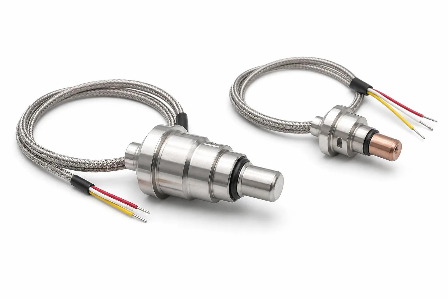
Bearing RTD Contact Assembly
Use this construction when Pt100 stability, insertion depth, lead protection, and protection-system compatibility drive the bearing-monitoring requirement.
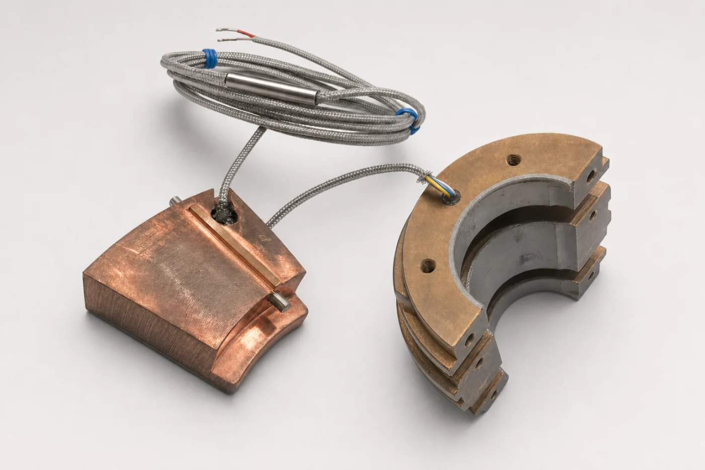
Typical Bearing Housing Inserts
The BRTD is the insert used for bearing temperature monitoring; the right-side example shows Babbitt material used around the bearing housing interface.
Bearing RTD Configuration Options
Stainless Contact Bearing RTD
The standard bearing RTD starting point is a Pt100 element with a stainless contact style for rugged bearing housing measurement, corrosion resistance, and long-term stability in motors, generators, turbines, turbo machinery, pumps, and gearboxes.
For turbine bearings, generator bearings, and turbo machinery, BRTD assemblies are typically part of a machine-protection strategy. Stable contact, repeatable insertion depth, protected lead routing, and compatibility with RTD input cards help operators track bearing metal temperature trends and trigger alarm or shutdown logic before damage develops.
Copper Contact Bearing RTD
Copper contact styles can be specified as a secondary option when the application benefits from higher thermal conductivity at the bearing interface. Stainless should remain the first-position construction unless the installation calls for copper contact behavior.
Mounting and Retention Options
Bearing RTDs can be configured around housing bore detail, insertion depth, contact force, lead protection, and retention method. Spring-loaded or bayonet hardware may be appropriate for repeatable-contact installations, but those details should not define the entire bearing RTD category.
API 670 Bearing Temperature Monitoring
API 670 (Machinery Protection Systems) specifies requirements for bearing and winding temperature monitoring on critical rotating equipment. Pt100 RTD sensors are commonly preferred over thermocouples for bearing temperature measurement because of their higher accuracy and better long-term stability.
Intrinsically Safe Bearing RTDs for Hazardous Areas
For hazardous-area rotating equipment, Thermometrics can support RX26-style intrinsically safe bearing RTDs. These are different from a standard explosion-proof connection-head assembly: the sensor construction, case, lead wire, element count, and accessory selection all have to stay inside the approved configuration.
Available Configuration Inputs
Certification and Lead Details
Typical Program Fits
Information to Share for Quoting
Need this product configured to your application?
Share the process conditions, geometry, connection details, and documentation requirements. We can help scope the right assembly.