Thermocouples
Thermocouples built around the measurement environment
Thermocouple selection starts with temperature range and atmosphere, but the finished assembly is usually determined by junction style, sheath material, diameter, insertion length, lead protection, termination, and documentation requirements.
Thermometrics builds base-metal and noble-metal thermocouple assemblies for industrial process control, aerospace testing, validation work, heat-treat programs, and OEM equipment where standard catalog probes do not fit the application.
Types K, J, T, E, N, R, S, and B are available in grounded, ungrounded, exposed, duplex, mineral-insulated, protection-tube, wire-sensor, surface-mount, and head-style constructions.
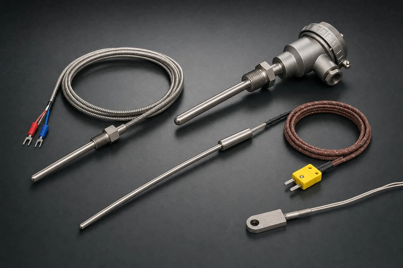
Thermocouple assembly family
Common mineral-insulated, armored, plug-and-lead, head-style, and surface thermocouple formats.
Types of Thermocouples
Builds are commonly specified to ASTM E230 and IEC 60584 tolerances, with standard or special limits of error depending on thermocouple type and application requirement.
Type B
1475 to 3270°F (800 to 1800°C). Clean air service; avoid reducing atmospheres.
Type E
-454 to 1600°F (-270 to 870°C). Highest EMF output; good for cryogenic use.
Type J
32 to 1382°F (0 to 750°C). Vacuum, oxidizing/reducing, or inert atmospheres.
Type N
-454 to 2300°F (-270 to 1260°C). Oxidizing, inert, or dry reduction atmospheres.
Type T
-454 to 700°F (-270 to 370°C). Moisture resistant and very stable at low temps.
Junction Styles
Information to Share for Quoting
Where These Thermocouple Builds Are Commonly Used
Browse Thermocouple Product Pages
Select the thermocouple construction by service condition: high-temperature MI cable, head-style plant assemblies, noble-metal furnace sensors, protection-tube builds, surface or tube-skin measurement, wire sensors, miniature probes, multipoint profiling, or plastics tooling sensors.
Harsh Process & Plant
For process installations, furnace environments, and durable field-service assemblies.
MI Cable Thermocouples
Mineral-insulated, metal-sheathed builds for harsh thermal and vibration environments.
View pageIndustrial Head Assemblies
Head-style thermocouple and RTD assemblies for process plants, transmitters, and maintainable field replacement.
View pageNoble Metal Thermocouples
Type R, S, and B assemblies for furnace, aerospace, and calibration-critical service.
View pageProtection Tube Thermocouples
Protected high-temperature assemblies for furnaces, kilns, and abrasive processes.
View pageSurface, Compact & OEM
For tight fit-up, external contact measurement, harnessed builds, and OEM packaging constraints.
Surface Mount Thermocouples
Ring, magnet, and weld-pad styles for pipe, vessel, and equipment surfaces.
View pageTube-Skin Thermocouples
Weld-pad and surface-contact probes for heater and furnace skin temperature.
View pageWire & Cable Sensors
Extension wire, bare junctions, and lead constructions for custom harnesses.
View pageMiniature & Needle Probes
Fine-wire and small-OD thermocouple probes for tight spaces, fast response, and compact fixtures.
View pageProfiling & Multi-Point
For distributed temperature measurement across ducts, vessels, heat-treat work zones, and other multi-zone systems.
Multipoint Thermocouples
Multi-zone assemblies for reactors, vessels, towers, and process profiling.
View pageRake Assemblies
Duct, stack, and gas-flow profile measurement with distributed sensing points.
View pageSpike & Profile Sensors
Thermocouple survey builds plus related profile-sensor applications for qualification and validation work.
View pageAveraging Sensors
Multi-junction thermocouple and wound-wire RTD averaging assemblies for ducts, plenums, tanks, and distributed measurement zones.
View pageDuplex / Dual-Element Assemblies
TC/TC, RTD/RTD, and mixed TC/RTD assemblies for redundancy, split instrumentation, and control/alarm separation.
View pageApplication-Specific
For specialized measurement programs tied to particular equipment classes and process geometries.
Gas Turbine Sensors
EGT and TIT thermocouple assemblies with related compressor measurement coverage for turbine systems.
View pageNozzle & Melt Thermocouples
Plastics-processing sensors for nozzles, barrels, and molded tooling points.
View pageIndustries Where Specialty Thermocouples Are Common
These industries most often require the broader mix of harsh-duty, profiling, miniature, and specialty thermocouple assemblies shown above.
Aerospace & Defense
Flight-test, engine, cryogenic, and qualification-driven thermocouple programs.
View industryMetals & Heat Treat
High-temperature furnace, survey, and noble-metal thermocouple applications.
View industryEnergy & Power
Turbine, heater, and severe-duty plant measurement points with elevated thermal demands.
View industryRequest a Thermocouple Quote
Need a specific material, connector, or junction configuration? Start a custom RFQ and our engineers will help specify the best solution.